
AI Therapist Extension
Innovation Design Engineering
The goal of this project was to explore the pain points of therapy and identify ways to support the user in moments of need.
Inspiration
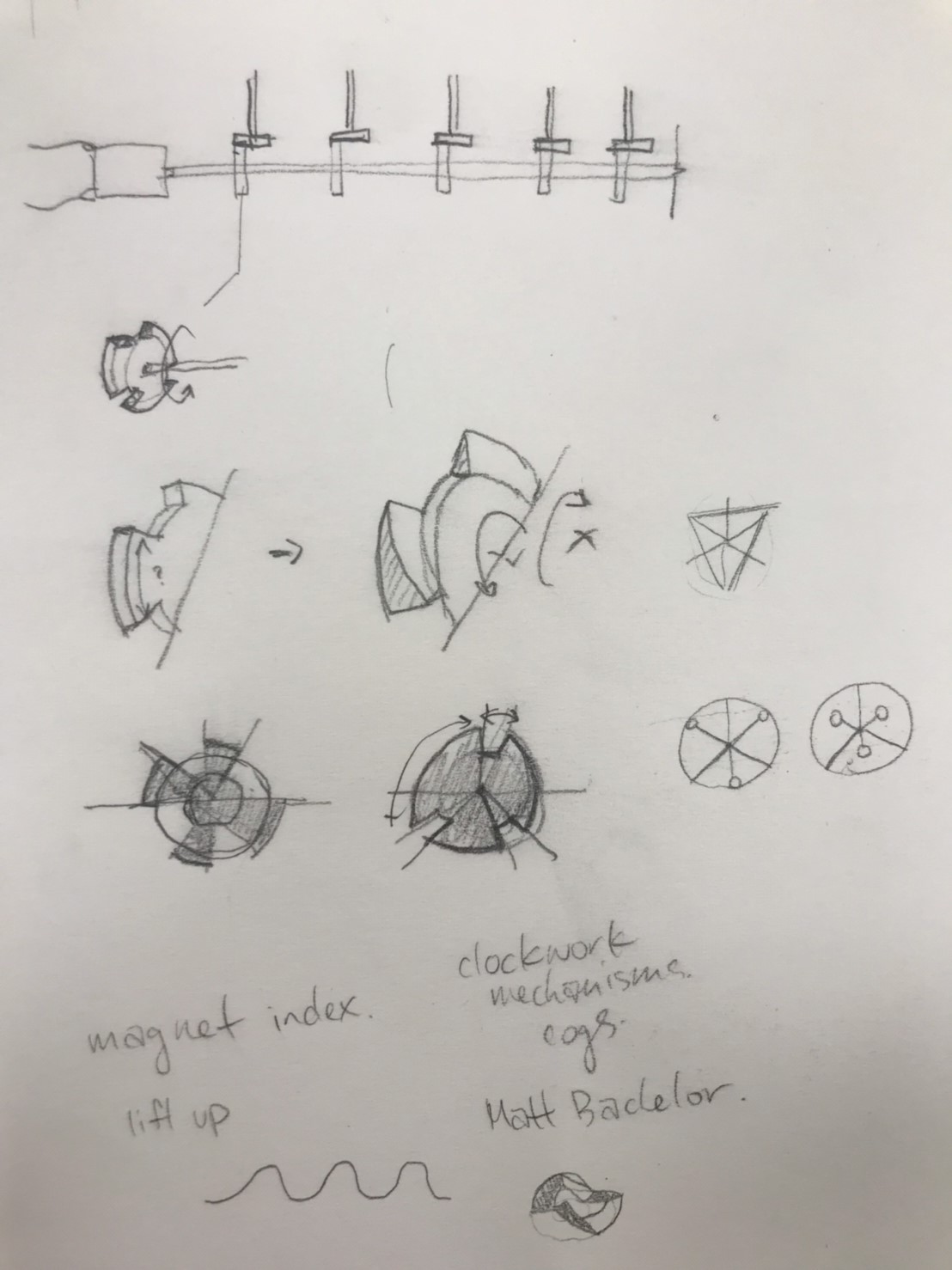
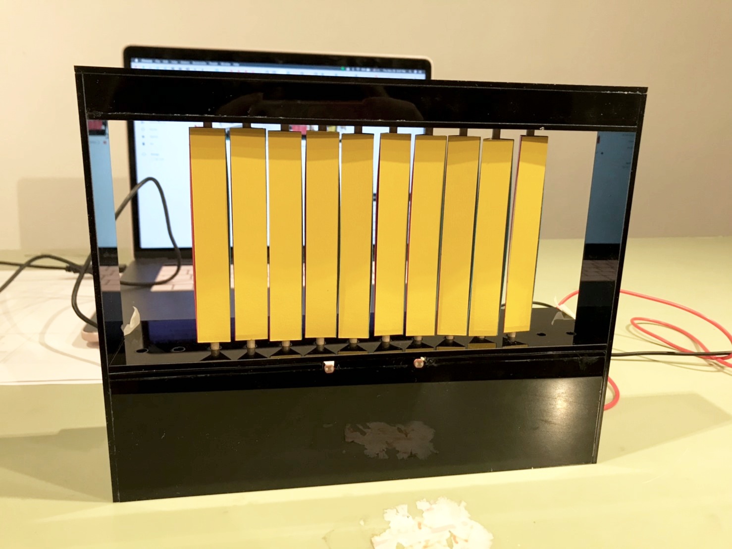
I wanted to recreate the soothing cascade of panels from the Design Museum’s “User Maker Designer” installation and add an interactive element. However, the installation uses individual motors that control each panel, which I simply don’t have the budget for. The majority of the time was spent looking at different physical mechanisms to identify which ones could be modified to serve my needs.
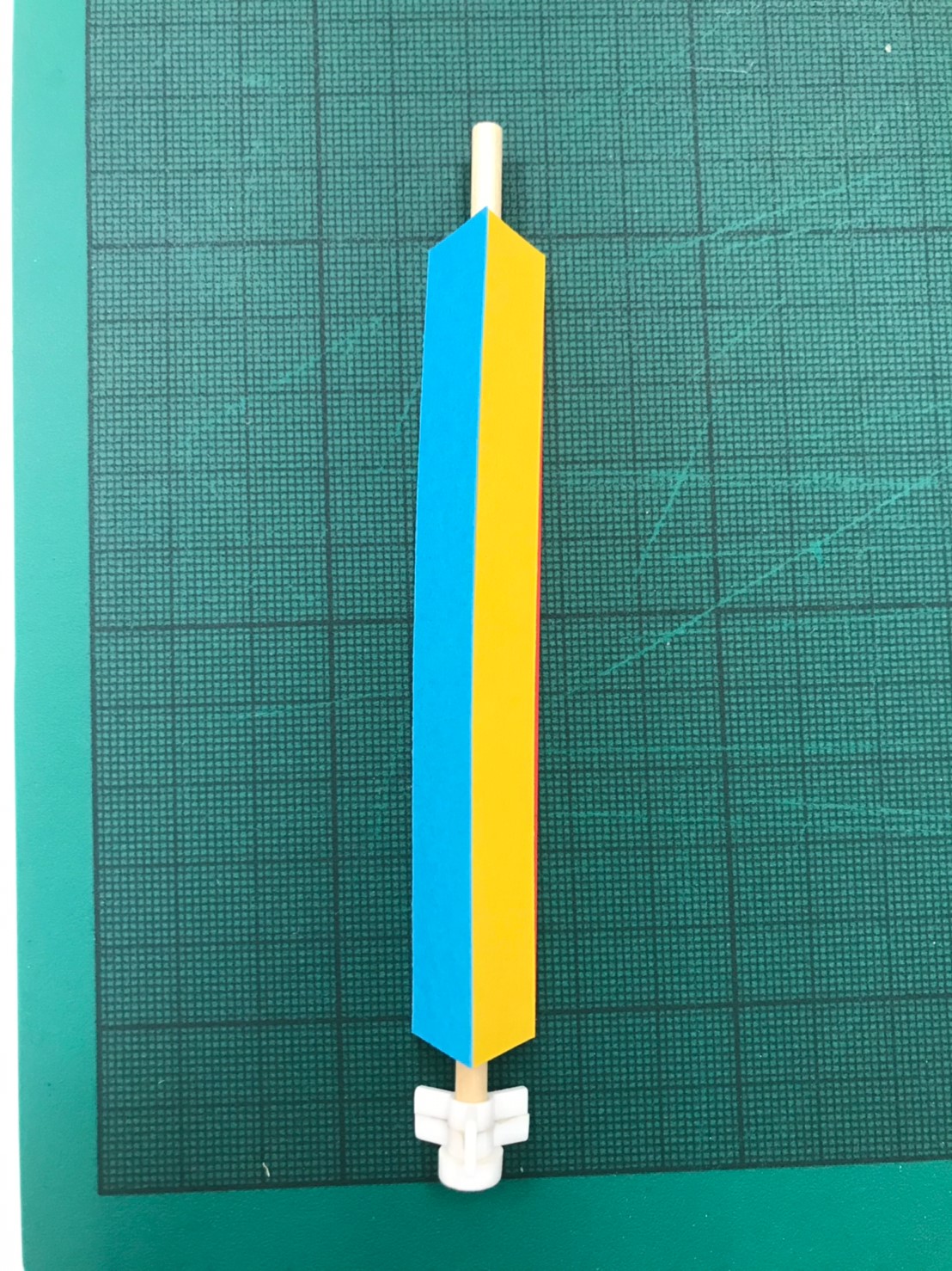
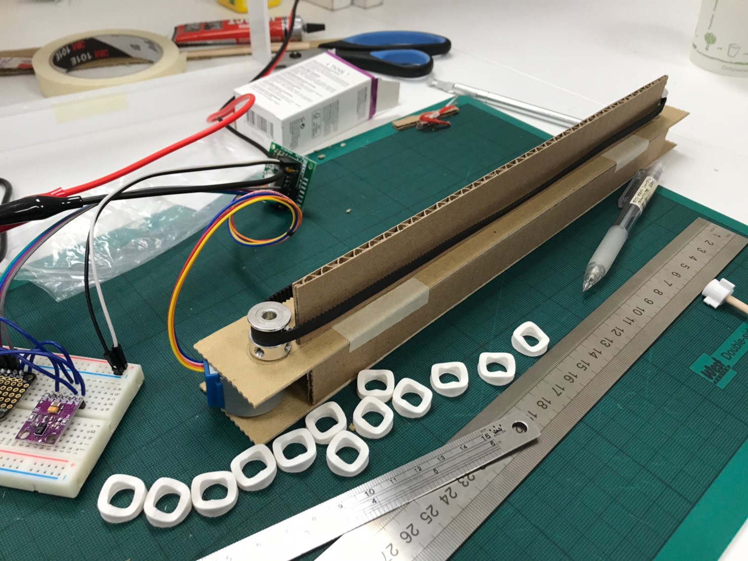
Prototyping
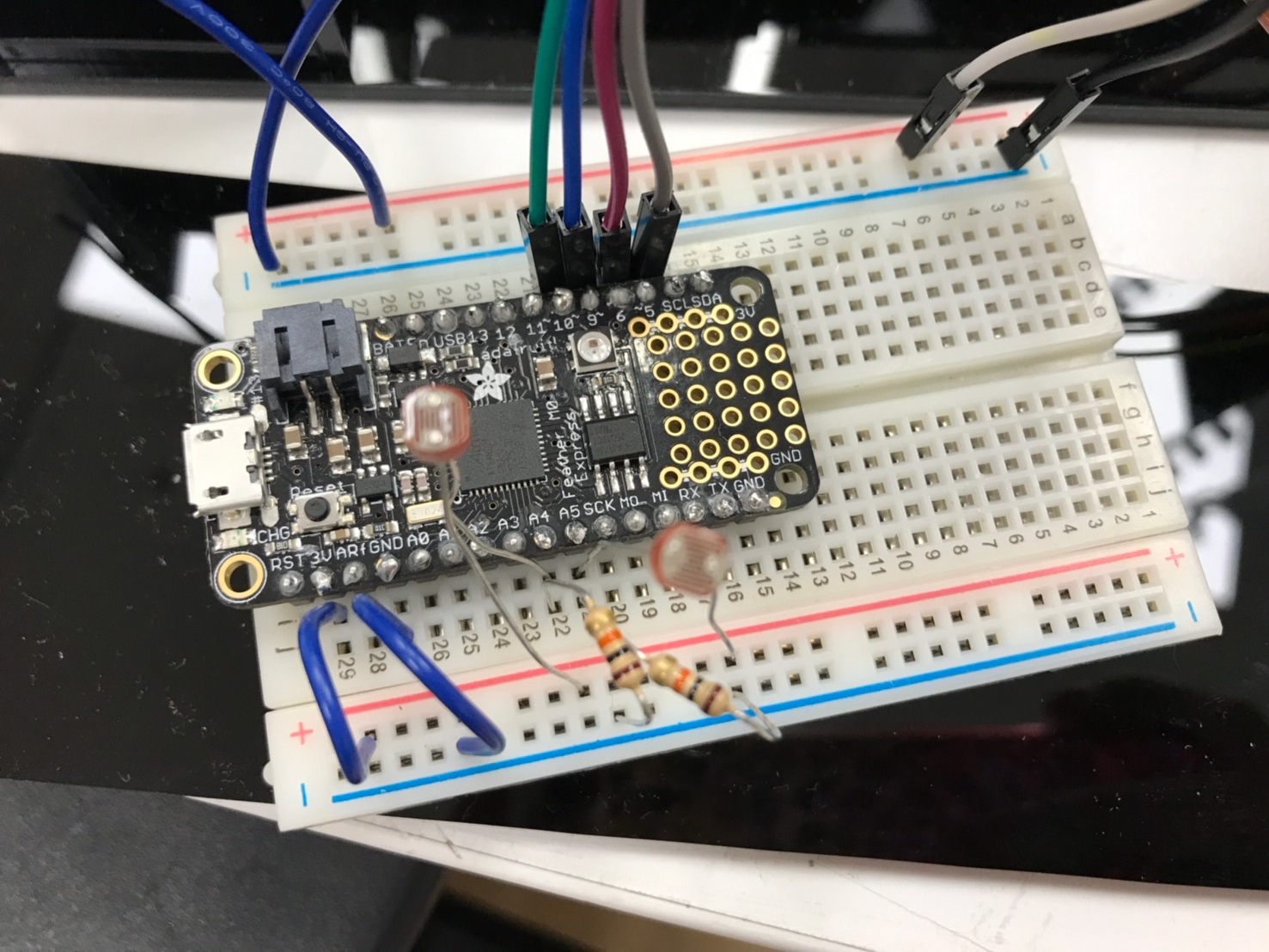
I started with simple cardboard models to test and validate designs before investing in the components. This project more than the others required good time management and timing as I had to take into consideration shipping time for components. Some components arrived and were broken, forcing me to make last minute functions from scratch to carry out the design. Originally, I had ordered a gesture sensor from a third party distributor, but when it arrived, it seemed the infrared sensors were broken. As a result, I had to quickly make my own gesture sensor by detecting the timing differences in light change between two light theremins. The end result was far from perfect, but I believe given more time, I could have a more polished gizmo. I learned that although I was confident in the electrical/coding component of the project, I should still take care to calculate errors and mishaps into the scheduling.


#include <AccelStepper.h>
#define HALFSTEP 8

// Motor pin definitions
#define motorPin1  10     // IN1 on the ULN2003 driver 1
#define motorPin2  9     // IN2 on the ULN2003 driver 1
#define motorPin3  6     // IN3 on the ULN2003 driver 1
#define motorPin4  5     // IN4 on the ULN2003 driver 1

//Time Variables
unsigned long startMillis;
unsigned long timing1; //time variable for left sensor
unsigned long timing2; //time variable for right sensor

//Sensor Variables
int sensorValue1; //left sensor
int sensorValue2; //right sensor
int sensorLow = 1023;
int sensorHigh = 0;

//Interaction Variables
boolean right = false;
boolean left = false;
boolean interaction = false;

// LED pin
const int ledPin = 13;

// Initialize with pin sequence IN1-IN3-IN2-IN4 for using the AccelStepper with 28BYJ-48
AccelStepper stepper1(HALFSTEP, motorPin1, motorPin3, motorPin2, motorPin4);


//***Main Code***

void setup() {
  // Make the LED pin an output and turn it on
  pinMode(ledPin, OUTPUT);
  digitalWrite(ledPin, HIGH);
  startMillis = millis();  //Initial start time

  // Calibrate for the first five seconds after program runs
  while (millis() < 5000) {
    //Set sensor values to read from the corresponding analog pins
    sensorValue1 = analogRead(A4);
    sensorValue2 = analogRead(A5);

    // record the maximum sensor value for sensor1
    if (sensorValue1 > sensorHigh) {
      sensorHigh = sensorValue1;
    }
    // record the minimum sensor value for sensor1
    if (sensorValue1 < sensorLow) {
      sensorLow = sensorValue1;
    }
    // record the maximum sensor value for sensor2
    if (sensorValue2 > sensorHigh) {
      sensorHigh = sensorValue2;
    }
    // record the minimum sensor value for sensor2
    if (sensorValue2 < sensorLow) {
      sensorLow = sensorValue2;
    }

  //Initialize motor settings
  stepper1.setMaxSpeed(1500.0);
  stepper1.setAcceleration(1000.0);
  stepper1.setSpeed(1000);
  stepper1.setCurrentPosition(0);

  digitalWrite(ledPin, LOW); // turn the LED off, signaling the end of the calibration period
  Serial.begin(9600); //Starts Serial communication
  }
}

void loop() {
//  //read the input from A0 and store it in a variable
//  sensorValue1 = analogRead(A5);
//  sensorValue2 = analogRead(A4);

  // map the sensor values to a wide range of pitches
  int reading1 = map(sensorValue1, sensorLow, sensorHigh, 50, 4000);
  int reading2 = map(sensorValue2, sensorLow, sensorHigh, 50, 4000);


  //Detect if valid interaction happened, if so, set interaction to TRUE
  if (stepper1.distanceToGo() == 0){ //check to see if stepper motor has reached the destination, if so, begin new loop and receive input, otherwise, continue moving the motor
    stepper1.setCurrentPosition(0); //if so, set the current location to be the new starting point
    if (reading1 < 0){ //if sensor1 detects negative light change, take the current running time of program and put it in timing1
      timing1 = millis();
      if (reading2 < 0){ //if sensor2 detects negative light change, take the current running time of program and put it in timing2
        timing2 = millis();
        if (timing1 - timing2 <= 100){ //if the time difference between timing1 and timing2 is less than 1 second, it means an interaction has happened
          interaction = true;
        }
      }
    }
    if (reading2 < 0){ //if sensor2 detects negative light change, take the current running time of program and put it in timing2
      timing2 = millis();
      if (reading1 < 0){ //if sensor1 detects negative light change, take the current running time of program and put it in timing1
        timing1 = millis();
        if (timing2 - timing1 <= 100){ //if the time difference between timing1 and timing2 is less than 1 second, it means an interaction has happened
          interaction = true;
        }
      }
    }

    //If an interaction has happened, check to see which timing came first to determine the direction of hand gesture
    if (interaction){
      if (timing1 < timing2){ //if the time sensor1 was triggered is earlier than time for sensor2, it means the interaction started from the left and moved to the right
        Serial.println("Right");
        stepper1.moveTo(-20000); //set the new motor destination 20000 units in the counter-clockwise direction, so the panels get turned starting from the left side, going to the right
        interaction = false; //reset the interaction boolean to false so the motor doesn't get accidentally triggered in the next iteration if no interaction was detected
        delay(400); //wait 4 seconds
      }
      if (timing2 < timing1){ //if the time sensor2 was triggered is earlier than time for sensor1, it means the interaction started from the right and moved to the left
        Serial.println("Left");
        stepper1.moveTo(20000); //set the new motor destination 20000 units in the clockwise direction, so the panels get turned starting from the right side, going to the left
        interaction = false; //reset the interaction boolean to false so the motor doesn't get accidentally triggered in the next iteration if no interaction was detected
        delay(400); //wait 4 seconds
      }
    }
  }
  stepper1.run(); //run the stepper motor
}